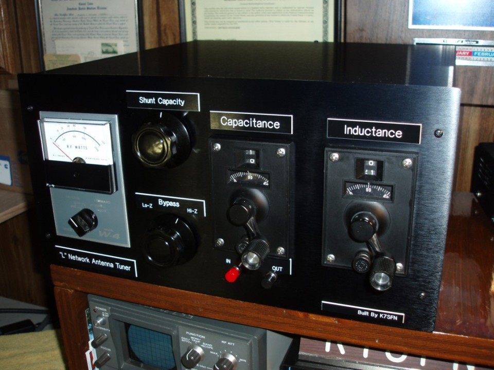
FINISHED "L" NETWORK ANTENNA TUNER
"L" Network Antenna Tuner Project Description:
I have always wanted a "HEAVY DUTY" antenna tuner that could take anything I could throw at it, and never break a sweat.
After doing some research and reading about the different types of tuners, I settled on a modified "L" Network design for the following reasons:
It has only two adjustable parts, one inductor and one capacitor; most other networks use three. Because there are no internal nodes in the network, the maximum circuit voltages and currents which occur are never more than those present at the input or output terminals. Because there are only two variable components, there is only one setting of each which will provide a perfect match to a given load impedance. This unique setting automatically provides the lowest Q network possible. Low Q means low circulating currents, and low loss.
Over a period of about three months, I managed to accumulate the necessary parts. The variable inductor, a key item, was given to me by a Ed, K6ED. I had seen similar inductors listed on EBay for reasonable prices. The Jennings UCSX-1000-10S, 1000pf-10kV vacuum variable, 680pf, 20kV doorknob caps, knobs, and 10amp RF switches were found on Ebay for very reasonable prices. I have always been fond of my old Drake W-4 wattmeter, and thought it would be a great addition to this project. Besides, it was just sitting on the shelf, collecting dust. The Jennings latching vacuum relays, and Millen Turns counters were obtained from Max-Gain systems, http://www.mgs4u.com/ , for reasonable prices.
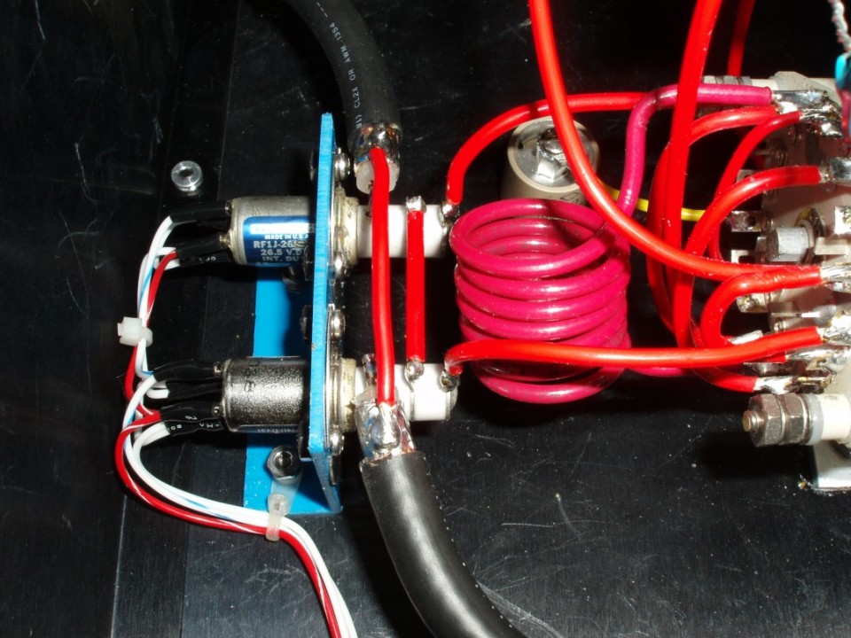
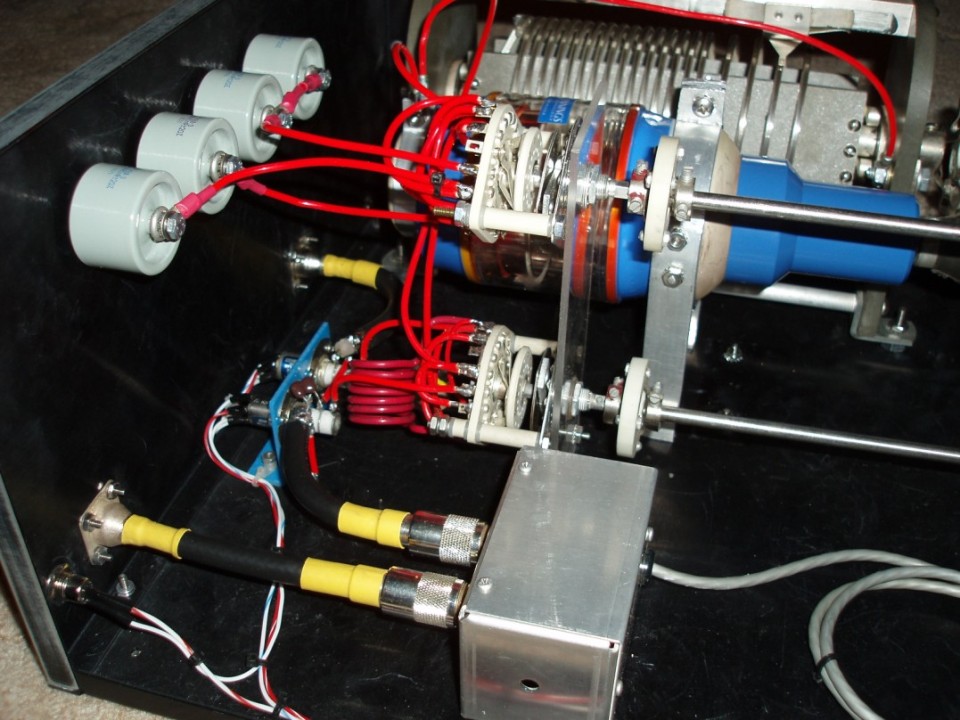
To power the latching relays, I found a large "Wall-wart" DC power supply (15V, 1A), and mounted a coaxial power connector on the back of the tuner. Two Push-Button switches provide power to the "latching" relays. Continuous power is not required. The latching relays provide for bypassing the tuner, when it is not required. I used a pair of Jennings RF1J relays, that are rated at 10 amps maximum at 60 hz., 7.5 amps at 32 Mhz. Contact test voltage 4 kv, and 3.6 kv rated working at 60 hz, and 3.2 kv rated working at 32 mhz. I thought this to be adequate for my design, since I did not plan on doing any "Hot Switching". In one of the close-up pictures you can see small disc ceramic caps on one of the relays. These disc ceramic caps have been replaced with a 33pf, 500V silver mica cap, and cancel the impedance bump caused by the relays when the tuner is in the By-pass mode.
For previous small projects, I had found the engraved plastic tags, with double sided sticky tape worked great, so that is what I did for the antenna tuner. I searched the internet, and found a company in the NW United States who made them for me for about $30 USD.
For the enclosure, I did a LOT of searching on the net. I finally purchased a Black brushed aluminum enclosure from Par-Metal Products in New Jersey at http://www.par-metal.com/ . Their prices we very reasonable and they had a large selection to choose from. I settled on one of their 20-Series Standard Sizes (8"x16"x16")
Layout of the components was done on a CAD program, which simplified things and helped prevent me from making mistakes :-)
I chose not to install an internal balun in my tuner, because, at that time, I did not have any open wire fed antennas. I have since installed a 1:1 remote balun in my garage that is fed with an 8' length of RG-213 from the shack. The antenna side of the balun is connected to 160 feet of 400 ohm ladder line, feeding my 160m center fed inverted vee.
So far, so good....I have been able to match any combination I need, and there is absolutely no signs of any component heating or arcing. The shunt capacity is only necessary on 160M and 80M to match my Inverted vee antennas at the band edges.
Should you be interested in "Homebrewing" a "L" Network tuner, a QST article in the October 2004 QST, Page 35 written by Jack Belrose, VE2CV, is worthwhile reading. My design was influnced by the TenTec 238/239 tuners, with significantly heavier components :-)
Good Luck,
73's Frank - K7SFN
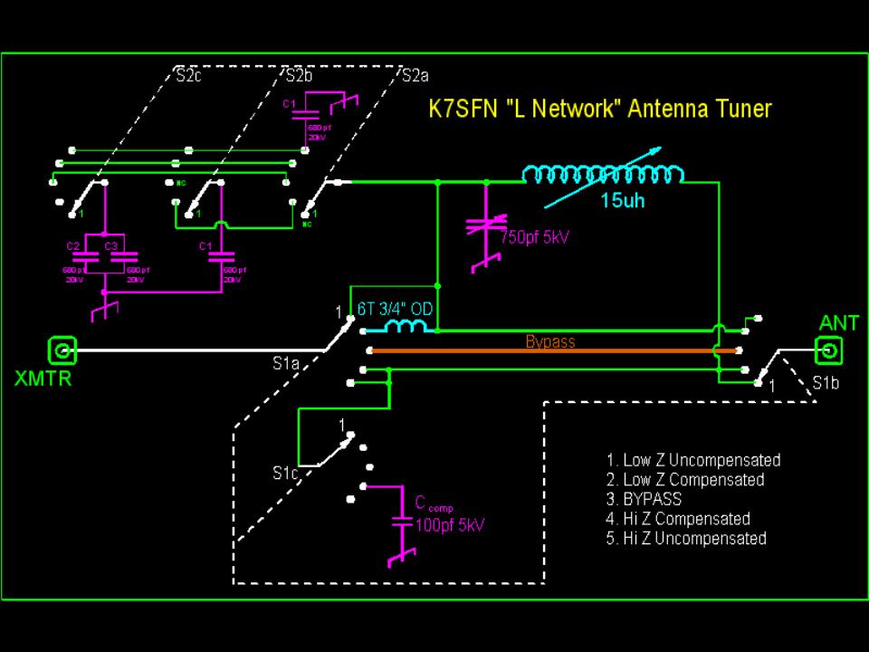
Schematic:
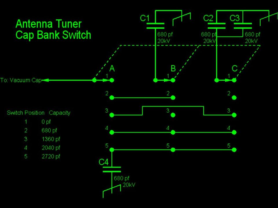
Capacitor Bank Switching Circuit
Inside View From Front Panel
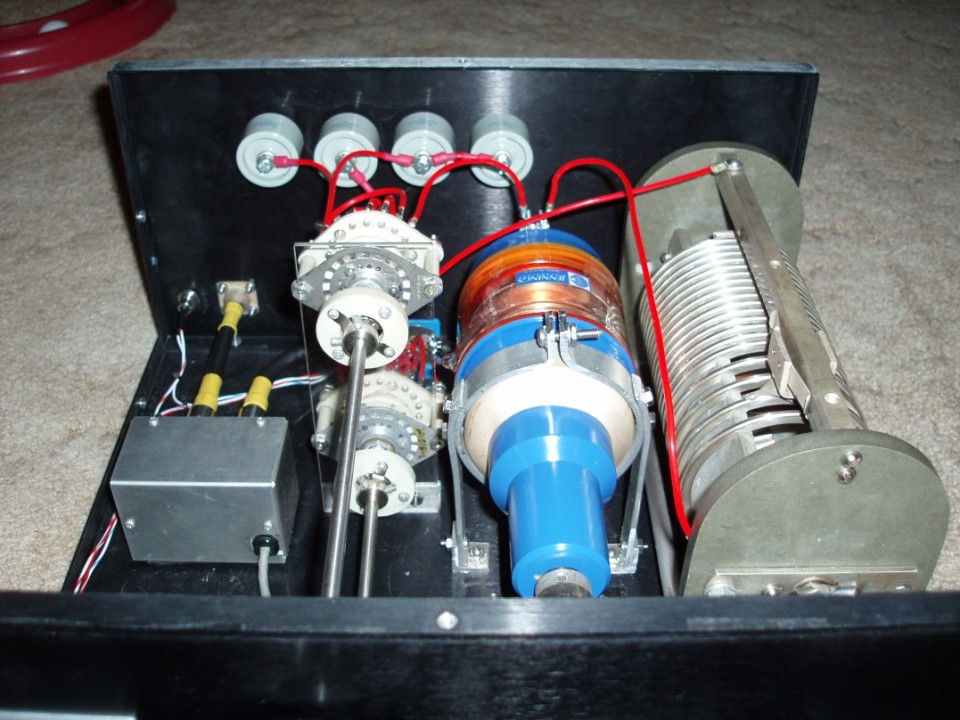
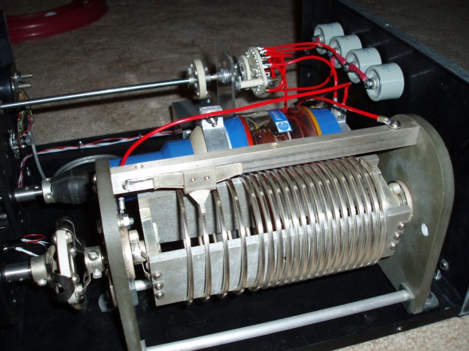
Inside View From Above Showing Jennings 1000pf 10kV Vacuum Variable
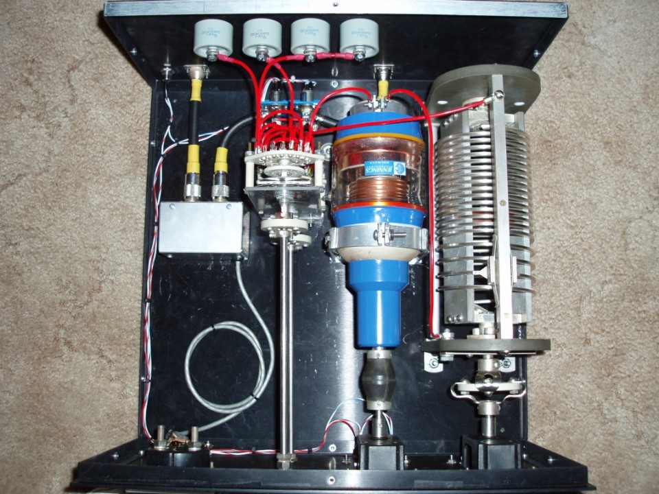
680pf 30kV Doorknob Caps for additional Shunt Capacity - Total Capacitance =3720 pf
Silver Plated Edge Wound Variable Inductor - 16 uh.
7500 Volt 10 Amp Jennings Latching Vacuum Relays for Tuner Bypass Control